


Project Central Gateway Terminal: Station Interior Coverage Solution for a Major Transit Hub in Chicago
Contractor Team Introduction
We are a Shenzhen based WiFi engineering contractor with extensive experience in transportation facilities, public buildings, commercial venues, hospitality properties, outdoor wireless transmission, and high traffic public WiFi environments. Our team has completed wireless coverage projects for railway stations, bus terminals, airport waiting areas, ferry terminals, shopping centers, hotels, government service halls, warehouses, and outdoor surveillance transmission sites.
Station interior WiFi is different from ordinary office WiFi. A transit hub has passenger concentration, high ceilings, metal structures, glass partitions, ticketing equipment, security devices, staff handheld terminals, retail tenants, surveillance cameras, public information systems, and long corridors. A successful station project must support both passenger access and operational systems without allowing guest traffic to affect business critical devices.
Our team has used COMFAST equipment in many indoor coverage and wireless transmission projects. From our field experience, COMFAST gateways, WiFi 6 routers, in wall APs, ceiling APs, paired wireless bridges, and PoE switches provide a practical balance of performance, installation flexibility, clean deployment, and long term maintainability. For this station project, we selected COMFAST equipment because the customer needed reliable indoor coverage, business network separation, CCTV wireless transmission, and a network structure that the station IT team could maintain after handover.
This case documents our Station Interior Coverage Solution for Central Gateway Terminal in Chicago. The project covered the entrance hall, ticketing area, automatic ticket machines, security check area, waiting hall, transfer corridor, platform waiting area, service counter, station office, staff rest area, retail shop area, underground passage, elevator lobby, stairwell entrances, CCTV points, and management equipment room.
1. Project Overview
Basic Project Information
Project Name: Project Central Gateway Terminal
Project Location: Chicago, Illinois, USA
Facility Type: Urban rail and bus transfer station
Interior Coverage Area: Approximately 38,000 square feet
Average Daily Passenger Flow: About 18,000 passengers
Peak Hour Passenger Flow: About 3,200 passengers
Project Type: Station Interior Coverage Solution with passenger WiFi, staff network, ticketing network, security network, camera network, and management network separation
Project Cycle: Five weeks from survey to final acceptance
Construction Window: Late evening and low traffic hours to avoid disruption to station operation
The station operations team contacted us after repeated complaints about unstable WiFi in the waiting hall, weak signal in the underground passage, dropped staff handheld terminal connections, and unreliable camera transmission in several remote corners of the facility. The existing network had grown over time without a unified design. Our task was to rebuild the station interior network into a clean, segmented, and professionally documented wireless system.
2. Customer Pain Points Before the Project
Passenger WiFi Was Unstable During Peak Hours
The waiting hall had a large number of passengers connecting at the same time during morning and evening rush hours. The old network could handle light traffic during quiet periods, but when hundreds of passengers tried to connect, the WiFi became slow and unstable. Passengers experienced failed connections, delayed loading, and poor roaming between the entrance hall and waiting hall.
Ticketing and Security Devices Were Affected by General Traffic
Some ticketing terminals and security check devices were connected through the same network environment as staff and public WiFi devices. When passenger traffic increased, business devices became less stable. Ticket validation and device status updates occasionally slowed down, creating pressure for the station operations team.
Underground Passage and Transfer Corridor Had Weak Signal
The underground passage had thick concrete walls, long narrow walking paths, and several turns. The existing APs in the main hall could not provide reliable signal into this area. The transfer corridor also had weak signal at both ends and unstable roaming in the middle section.
Station Staff Handheld Terminals Dropped Connection
Station staff used handheld terminals for ticket assistance, passenger service, inspection records, and internal communication. These terminals moved between the service counter, waiting hall, platform access area, and staff office. The original WiFi design did not support smooth roaming, so devices sometimes held onto a weak AP signal instead of switching properly.
Remote CCTV Points Were Difficult to Cable
Several camera locations near the underground passage entrance and remote platform waiting zone were difficult to cable without opening finished surfaces or interrupting station operation. The customer wanted stable video transmission without large scale construction.
All Networks Were Poorly Separated
Passenger WiFi, staff devices, ticketing devices, retail tenant devices, cameras, and management equipment were not clearly separated. This made troubleshooting difficult and increased security risk. The station needed a structured network design with clear device groups and policies.
3. Customer Requirements
Confirmed Requirements from Station Operations
Stable passenger WiFi coverage across the main station interior.
Reliable coverage in the entrance hall, ticketing area, security check area, waiting hall, transfer corridor, underground passage, and platform waiting area.
Separate passenger WiFi, ticketing and security network, staff network, camera network, retail tenant access, and management network.
Stable connectivity for staff handheld terminals while moving through the station.
Priority protection for ticketing terminals and security devices.
Wireless bridge transmission for CCTV locations where new cabling was not practical.
PoE powered AP deployment to reduce local power adapters and simplify maintenance.
Clean installation without disrupting normal station operation.
Final documentation, port labeling, AP location records, and IT handover training.
4. COMFAST Equipment List and Reasons for Use
The following are the main COMFAST equipment models used in this project and their usage descriptions.
| Equipment Modelis |
Type | Project Use | Reason for Use |
|---|---|---|---|
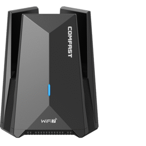
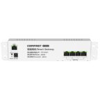
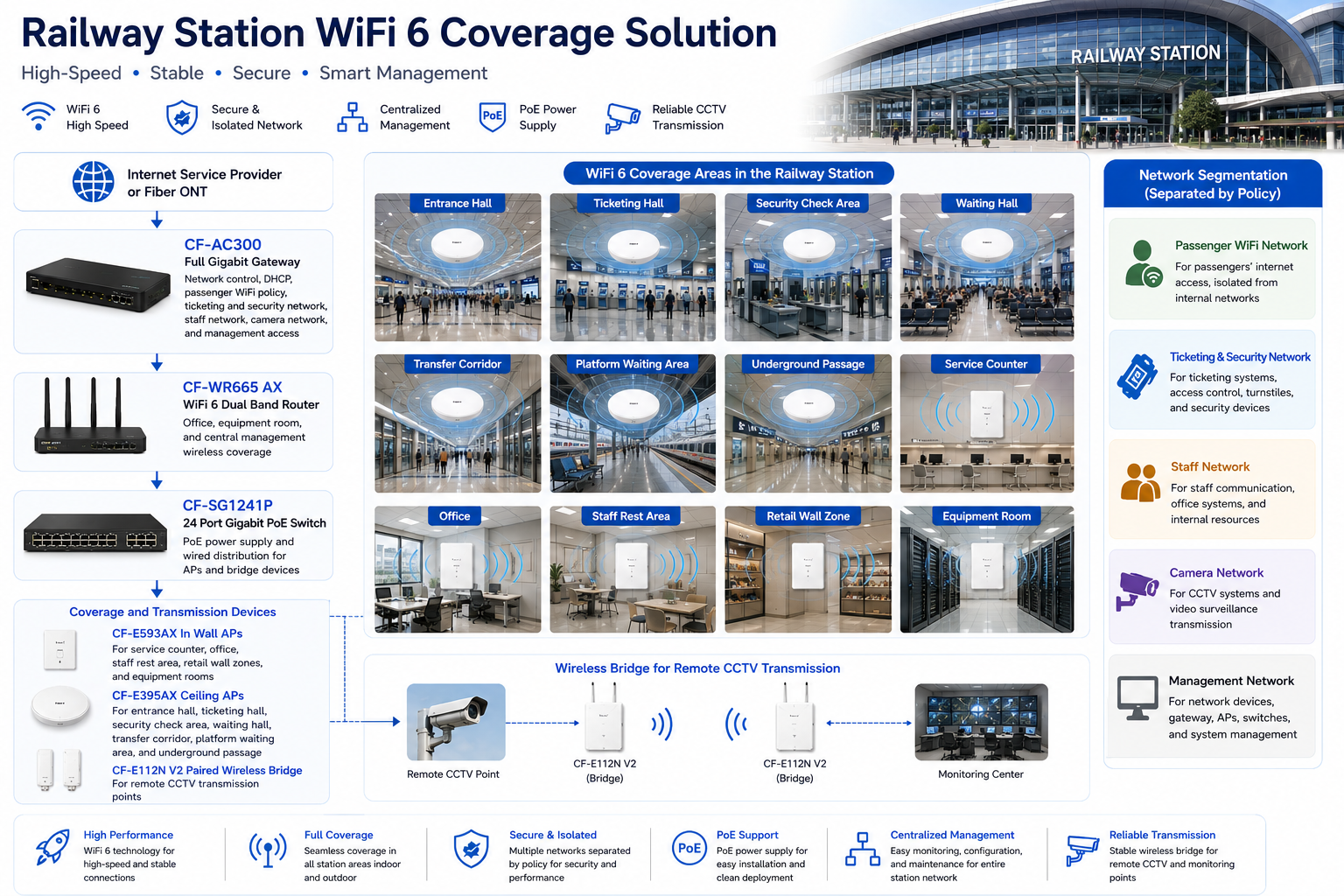
| CF-AC300 | Full gigabit gateway | Central gateway, internet access, DHCP assignment, passenger WiFi policy, ticketing and security network policy, staff network policy, camera network planning, and management access | Suitable as the station central gateway, keeping business-critical systems protected from general passenger traffic |
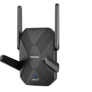
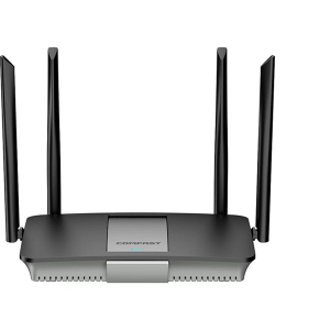
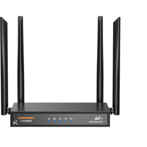
| CF-WR665AX | WiFi 6 dual-band router | Office zone, management zone, IT maintenance access, and equipment room area coverage | Provides stable WiFi 6 dual-band coverage for station administration, maintenance, and management devices |
| CF-E593AX | Į sieną įmontuotas AP | Service counters, office rooms, staff rest areas, retail wall zones, and equipment rooms | Suitable for clean room-level coverage in areas where ceiling mounting is not ideal |
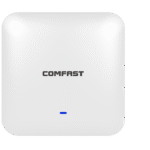
| CF-E395AX | Lubų AP | Entrance hall, ticketing area, security check area, waiting hall, transfer corridor, platform waiting area, underground passage, elevator lobby, and stairwell entrance zones | Suitable for broad indoor station coverage, high passenger density areas, and long walking-route coverage |
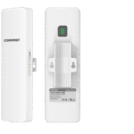
| CF-E112N V2 | 2.4G paired wireless bridge | CCTV wireless transmission for remote monitoring points where Ethernet cabling was difficult | Avoids opening finished areas and reduces impact on station operation while maintaining stable video transmission |
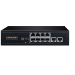
| CF-SG1241P | 24-port gigabit PoE switch | Power supply and Ethernet connection for APs and selected network devices | PoE deployment reduces wiring complexity, centralizes power delivery, and makes later maintenance easier for station IT staff |
5. Project Equipment Configuration Quantity
Based on station interior area, passenger flow, business network separation, CCTV transmission needs, and management requirements, the actual equipment deployed in this project was as follows:
| Equipment Model | Quantity | Deployment Location |
|---|---|---|
| CF-AC300 | 1 unit | Main equipment room, used as the station central gateway |
| CF-WR665AX | 1 unit | Office and management zone, IT maintenance area, equipment room area |
| CF-E593AX | Multiple units | Service counters, office rooms, staff rest areas, retail wall zones, equipment rooms |
| CF-E395AX | Multiple units | Entrance hall, ticketing area, security check area, waiting hall, transfer corridor, platform waiting area, underground passage, elevator lobby, stairwell entrances |
| CF-E112N V2 | Several pairs | Remote CCTV points near the underground passage entrance and platform waiting zone |
| CF-SG1241P | Multiple units | Main equipment room and AP distribution points for PoE power supply and wired network connection |
6. Project Topology Diagram
Overall Network Topology
7. Site Survey and Troubleshooting Process
Station Structure and RF Survey
We performed a full walkthrough of the station and tested signal behavior in every key area. The entrance hall and waiting hall had high ceilings and wide open areas. The transfer corridor was long and narrow. The underground passage had concrete walls and limited signal penetration. The platform waiting zone had metal structures and glass partitions that created reflection and attenuation.
Passenger Density Evaluation
We reviewed passenger flow patterns with the operations team. Morning and evening peak hours concentrated users in the entrance hall, ticketing area, security check line, and main waiting hall. This helped us determine AP placement and avoid relying on a few high power APs to cover the entire station.
Ticketing and Security Device Inspection
We inspected automatic ticket machines, service counter terminals, handheld ticketing devices, and security check network devices. These devices were treated as business critical and were separated from passenger WiFi traffic.
CCTV Transmission Path Survey
Several camera locations were difficult to cable without disrupting station finishes. We checked wireless transmission paths and selected CF-E112N V2 bridge pairs for camera backhaul where wired cabling was not practical.
Network Cabinet Inspection
The existing low voltage room had mixed cables and incomplete labels. We tested cable routes, verified AP drops, organized patching, and prepared the gateway and PoE switch installation layout. This work was essential for future maintenance.
8. Problems Found During Implementation
High Ceilings Caused Uneven Coverage
The waiting hall had a high ceiling and large open space. If APs were installed only according to ceiling convenience, signal would be uneven at passenger level. We adjusted AP locations based on real measurement points and passenger seating areas.
Metal Structures Created Signal Reflection
Metal beams, signage frames, ticketing equipment, and security structures created reflection and local interference. We adjusted AP power and channel planning to reduce co channel interference and prevent unstable client behavior.
Underground Passage Needed Dedicated AP Coverage
The underground passage could not be covered from the main hall. We installed dedicated CF-E395AX ceiling APs along the passage and tuned power to provide stable walking coverage without unnecessary overlap.
Business Devices Needed Network Separation
Ticketing, security, staff devices, retail tenants, cameras, and passenger WiFi had different stability and security needs. We separated them by policy through the gateway to prevent passenger usage from affecting station operation.
Construction Had to Avoid Passenger Disruption
The station could not close during the project. We used phased installation during low traffic windows, coordinated with operations staff, and completed testing zone by zone. This reduced operational risk and kept public areas available.
9. Final Engineering Solution
Core Network Design
The CF-AC300 was installed as the central gateway. The CF-SG1241P PoE switch handled AP power and wired distribution. The CF-WR665AX covered the office and management zone. Public and business networks were separated by policy to protect station operations.
Passenger Area WiFi Design
CF-E395AX ceiling APs were deployed in the entrance hall, ticketing area, security check area, waiting hall, transfer corridor, platform waiting area, and underground passage. AP locations were selected based on actual passenger positions, not only ceiling availability.
Staff and Office Coverage
CF-E593AX in wall APs were installed in staff offices, service counters, staff rest areas, and retail wall zones. This provided clean local coverage without interfering with public area APs.
CCTV Wireless Transmission
CF-E112N V2 paired wireless bridges were deployed for remote CCTV points. After alignment, we tested video stability, delay, and connection continuity before final acceptance.
10. Different Area Network Design
Entrance Hall Coverage
The entrance hall required stable WiFi for passenger access, staff handheld devices, and service information. Ceiling APs were placed to cover walking paths and waiting points near the main doors.
Ticketing Area Coverage
The ticketing area was treated as a business critical zone. Ticketing terminals and service counter devices were separated from passenger WiFi. AP coverage was tuned to support staff movement and customer service points.
Security Check Area Coverage
The security check area included scanning equipment, staff devices, and passenger queues. We planned coverage to avoid dead zones around equipment and reduced interference near metal structures.
Waiting Hall Coverage
The main waiting hall required capacity and coverage. CF-E395AX ceiling APs were placed to support passenger seating zones, information screens, and walking paths. Power and channels were tuned to reduce AP overlap.
Transfer Corridor and Underground Passage Coverage
The transfer corridor and underground passage were long and narrow. Dedicated ceiling APs were installed at planned intervals to support smooth roaming and avoid signal gaps in the middle sections.
Platform Waiting Area Coverage
The platform waiting area had metal structures, glass barriers, and passenger movement. AP placement was adjusted after field testing to avoid unstable signal around structural elements.
Retail Shop Area Coverage
Retail tenants needed stable connectivity for POS and daily business devices. Retail access was separated from passenger WiFi and staff networks, making tenant support easier.
Staff Office and Management Network
Staff offices and management devices used restricted network access. The management network was used for gateway, AP, switch, and bridge maintenance, keeping system administration separate from user traffic.
11. What We Did Differently from Other Engineering Teams
We Designed Around Station Operation
We did not simply add APs. We studied passenger flow, ticketing operations, security check movement, staff routes, retail needs, and camera transmission requirements before finalizing the design.
We Protected Business Critical Networks
Passenger WiFi was separated from ticketing, security, staff, camera, retail, and management networks. This prevented public usage from affecting station systems.
We Tuned the Network Instead of Using Maximum Power
High transmit power is not a professional solution in a station. We tuned channels and AP power to reduce interference, support roaming, and improve stability.
We Controlled Construction Impact
We worked in low traffic windows, used phased installation, and avoided disrupting passenger flow. This was critical for a station that continued operating during the project.
We Delivered a Maintainable System
We labeled every key connection, documented AP locations, recorded wireless bridge points, and trained the IT team. The final system was designed for long term maintenance, not just installation day success.
12. Installation and Optimization Details
Cable Testing and Cabinet Cleanup
We tested available cable routes, relabeled patch panel connections, and organized the low voltage room. The CF-AC101 gateway and CF-SG181P PoE switch were installed in a clean cabinet layout.
AP Mounting
CF-E395AX ceiling APs were installed in public areas, corridors, and underground passage zones. CF-E593AX in wall APs were installed in office, service counter, staff, and retail areas. Each AP location was checked for coverage, safety, appearance, and maintenance access.
Wireless Bridge Alignment
CF-E112N V2 bridge pairs were aligned carefully for remote CCTV transmission. We tested video feeds over time to ensure stable operation.
Roaming and Load Testing
We tested walking routes from entrance hall to ticketing, ticketing to security, security to waiting hall, waiting hall to transfer corridor, and underground passage to platform waiting area. Staff handheld terminals were tested during movement to confirm stable roaming.
13. Project Acceptance Results
Final Acceptance Checklist
Entrance hall WiFi coverage test passed.
Ticketing area business network test passed.
Security check device network test passed.
Waiting hall passenger WiFi test passed.
Transfer corridor roaming test passed.
Underground passage coverage test passed.
Platform waiting area coverage test passed.
Staff handheld terminal movement test passed.
Retail tenant network access test passed.
CCTV wireless bridge transmission test passed.
Passenger and business network isolation test passed.
Network labeling, AP location documentation, and IT handover completed.
14. Customer and User Feedback
Station Operations Manager Feedback
The station operations manager said, “The new network is much more organized than the previous setup. Passenger WiFi is stable, and our operational devices are no longer affected by public traffic.”
IT Supervisor Feedback
The IT supervisor said, “The labeling and network separation make maintenance much easier. We can now identify AP locations and device groups quickly instead of guessing.”
Ticketing Staff Feedback
Ticketing staff reported that service counter devices stayed connected more consistently during busy periods, which reduced delays for passengers.
Passenger Feedback
Passengers in the waiting hall reported faster connection and better stability. The underground passage and transfer corridor also became usable WiFi areas instead of dead zones.
15. Project Summary
Final Result
Project Central Gateway Terminal was a successful Station Interior Coverage Solution for a major transit hub in Chicago. The project solved passenger WiFi instability, weak underground coverage, poor corridor roaming, mixed network structure, ticketing device exposure, and remote CCTV transmission challenges.
The final COMFAST solution used the CF-AC101 full gigabit gateway, CF-WR633AX V2 WiFi 6 dual band router, CF-E593AX in wall APs, CF-E395AX ceiling APs, CF-E112N V2 paired wireless bridge, and CF-SG181P 8 port gigabit PoE switch.
The key value of this project was not only stronger WiFi. The real value was a structured station network that supported passengers, staff, ticketing systems, security devices, retail tenants, cameras, and management access without mixing everything into one unstable environment.
16. Lessons Learned and Advice to Other Contractors
Lessons Learned
Station WiFi must be designed around passenger flow and business device protection.
High ceilings and large halls require field tested AP placement, not guesswork.
Underground passages and long corridors need dedicated coverage planning.
Passenger WiFi, ticketing systems, security devices, staff terminals, cameras, and management access must be separated.
Wireless bridges are useful for CCTV points where new cable installation would disrupt operation.
Construction planning is as important as network design in an operating station.
Advice to Other Contractors
For station interior WiFi projects, do not simply increase AP quantity. Walk the passenger routes, check ticketing areas, observe waiting hall density, inspect underground passages, test platform waiting areas, and understand staff workflows before designing the network.
Do not place passenger WiFi and station operation devices on the same network. A public transportation facility depends on stable business systems, and those systems must be protected from passenger traffic.
A station WiFi project is complete only when passengers can connect smoothly, staff terminals remain online, ticketing devices stay stable, cameras transmit reliably, and the IT team can maintain the system confidently. That was the standard we delivered for Project Central Gateway Terminal.